Halo sahabat duino pada kali ini saya ingin memberikan tutorial cara mengakses sensor PIR menggunakan arduino.
Sensor PIR merupakan sensor yang mempunyai fungsi
sebagai pendeteksi adanya benda atau tidak dengan sistem deteksi
pancaran sinar infra-red. Kepajangan dari PIR yaitu Passive Infra-Red.
Komponen elektronika ini mempunyai sifat pasif, yang artinya tidak
dapat menghasilkan sinar infra-red secara independen akan tetapi hanya
bertindak sebagai penerima dari radiasi sinar infra-red.
Aplikasi penggunaan dari sensor PIR ini difungsikan dalam aplikasi
proyek detektor pergerakan. Dikarenakan semua benda yang memancarkan
atau menghasilkan energi radiasi, akan terdeteksi oleh sensor ini pada
saat infra merah dari sensor PIR mendeteksi dengan perbedaan suhu
tertentu.
Contoh dalam kehidupan sehari – hari yaitu pada saat memasuki pintu
Mall yang membuka dengan otomatis saat kita akan memasuki area dalam
Mall.
Prinsip Kerja Sensor PIR
Pancaran dari sinar infra-red yang mengenai ke sensor Pyroelektrik
masuk melalui lensa fresnel akan dihasilkan output arus listrik efek
dari sinar infra-red yang memiliki kandungan energi kalor.
Bahan dasar dari pembuatan sensor pyroelektrik yaitu cesium nitrat (CsNo3), galium nitrida (GaN), serta litium tantalate (LiTaO3).
Arus listrik yang timbul akan menghasilkan tegangan yang akan
diproses lebih lanjut yang dimana akan masuk ke IC kompator.Pada IC
komparator inilah akan dibandingkan tegangan yang dihasilkan dari hasil
pembacaan sensor dengan tegangan referensi /Vref dan akan menghasilkan
output berupa sinyal 1 bit.
Sehingga output dari sensor ini yaitu berupa logika 1 /high dan 0
/low. Pada saat konidisi logika HIGH berarti sensor terdeteksi adanya
infra-red, sedangkan logika LOW kebalikan dari itu.
Sensor ini difungsikan untuk mendeteksi adanya pancaran infra-red
yang panjang gelombangnya antara 8-14 μm, dan selain panjang gelombang
tersebut maka sensor tidak akan bekerja.
Pada manusia memupunyai temperatur suhu badan yang bisa menghasilkan
pancaran infra- red yang panjang gelombangnya antara 9-10 μm dengan
standar pada 9,4 μm. Dan pada nilai panjang gelombang tersebut merupakan
range nilai yang dapat dideteksi oleh sensor PIR.
#define waktutunda 5 //untuk 5 detik

const int ledPin = 13; //Menggunakan led built in Arduino
const int SensorPir = 2; //menggunakan pin ke-2 arduino

unsigned long now = millis();
unsigned long TriggerAkhir = 0;
boolean waktumulai = false;

void setup() {
  Serial.begin(115200); //baut komunikasi serial monitor

  pinMode(SensorPir, INPUT_PULLUP);
  attachInterrupt(digitalPinToInterrupt(SensorPir), deteksigerakan, RISING);

  pinMode(ledPin, OUTPUT);
  digitalWrite(ledPin, LOW);
}

void loop() {
  now = millis();
  if(waktumulai && (now - TriggerAkhir > (waktutunda*1000))) {
    Serial.println("Tidak ada gerakan!");
    digitalWrite(ledPin, LOW);
    waktumulai = false;
  }
}

void deteksigerakan() {
  Serial.println("GERAKAN TERDETEKSI");
  digitalWrite(ledPin, HIGH);
  waktumulai = true;
  TriggerAkhir = millis();
}
Pada saat sensor terpasang dan tidak mendeteksi adanya benda bergerak
didepannya maka lampu LED secara default padam, dan akan menyala dalam
waktu delay selama 5 detik.
Hallo Semuanya pada hari ini saya akan membagikan tutorial tentang bagaimana cara mengakses Motor servo menggunakan arduino.
Sebelum itu kita harus tau apa itu Motor Servo.
Motor servo adalah komponen elektronika yang berupa
motor yang memiliki sistem feedback guna memberikan informasi posisi
putaran motor aktual yang diteruskan pada rangkaian kontrol
mikrokontroler.
Pada dasarnya motor servo banyak digunakan sebagai aktuator yang membutuhkan posisi putaran motor yang presisi.
Apabila pada motor DC biasa hanya dapat dikendalikan kecepatannya
serta arah putaran, lain halnya pada motor servo yaitu penambahan
besaran parameter yang dapat dikendalikan berdasarkan sudut/derajat.
Komponen utama penyusun motor servo antara lain motor DC, gear rasio,
potensiometer serta controller servo seperti gambar dibawah ini.
Adanya komponen potensiometer difungsikan sebagai feedback nilai yang akan diolah menjadi data posisi aktual.
Sedangkan fungsi dari controller servo yaitu memberikan sinyal –
sinyal PWM (Pulse Width Modulator) untuk menggerakan motor melalui kabel
motor.
Macam tipe – tipe dari motor servo ini ada 2 yaitu tipe standard dan tipe Continous.
- Tipe standar berputarnya dibatasi sebesar 180° dan tipe ini sering banyak dipakai pada sistem robotika seperti Arm Robot / Robot Lengan.
Pada setiap body servo terdapat informasi akan identitas tipe servo
tersebut. Secara standar, motor servo terdiri atas 3 kabel yaitu kabel
power / VCC, kabel GND serta kabel signal
Tutorial mengakses motor servo dengan Arduino Uno
Pada tutorial kali ini akan dicontohkan eksperimen dengan motor servo
jenis mikro yang banyak dijual di pasaran dengan harga terjangkau.
Motor servo ini disebut micro servo dikarenakan ukurannya yang kecil dan memutuhkan tegangan atau arus yang kecil pula.
Spesifikasinya kurang lebih sebagai berikut :
- tegangan kerja : 4,8 – 6 Vdc
- torsi : 1,6 kg/cm
- arus : < 500 mA
- dimensi : 22 x 12,5 x 29,5 cm
- berat : 9 gr
- kecepatan putaran: 0,12 detik/60 derajat
Bahan yang perlu dipersiapkan antara lain :
- Arduino Uno
- Komputer + Software IDE Arduino
- Micro Servo
- Kabel Jumper
Keterangan :
Warna merah servo, dihubungkan ke pin 5V Arduino
Warna hitam/coklat servo, dihubungkan ke pin Gnd Arduino
Warna orange servo (kabel data/perintah), dihubungkan ke pin 9 Arduino (dapat digunakan pin lainnya)
Peletakan Library pada OS :
1. Mac : (home directory)/Documents/Arduino/libraries
2. PC (Windows) : My Documents -> Arduino -> libraries
3. Linux : (home directory)/sketchbook/libraries
Contoh kode pemrograman sederhana
#include <servo .h=""> // menyertakan library servo ke dalam program
Servo myservo;     // variable untuk menyimpan posisi data
int pos = 00;

void setup(){
 myservo.attach(3); //sinyal data kabel motor servo dikonekan di pin 3 Arduino
}

void loop(){
 for(pos = 00; pos < 180; pos += 1)  //fungsi perulangan yang akan dijadikan PWM dengan kenaikan 1
 {
  myservo.write(pos); //prosedur penulisan data PWM ke motor servo
  delay(15); //waktu tunda 15 ms
 }
 for(pos = 180; pos>=1; pos-=1)  //fungsi perulangan yang akan dijadikan PWM dengan penurunan 1
 {
  myservo.write(pos);
  delay(15);
 }
}
Keterangan program :
Untuk progam di atas, sudut putaran yang dapat dituju maksimal yaitu 180°. Sehingga menjadi batasan range posisi derajat yang dapat digunakan yaitu 0 – 180°.
Dengan menggunakan servo ini sudah tidak berbicara lagi mengenai
putar searah (Clock Wise) atau berlawanan arah jarum jam (Clock Counter
Wise) tapi sudut 0, 45, 90 dan seterusnya sampai dengan 180.
Apabila ingin mendapatkan posisi 90° dan bergerak berlawanan arah jarum jam maka dituliskan perintah myservo.write (90); setelah itu dituliskan myservo.write (0);.
Akan tetapi jika ingin mendapatkan posisi 90° dan serarah jarum jam maka dituliskan perintah myservo.write (90); setelah itu dituliskan perintah myservo.write (180);.
Jadi posisi 0 s.d 180 sudah ditentukan oleh
kontroller internal motor servo, dan cukup dengan memberikan perintah
pada sudut mana motor akan berputar melalui perintah myservo.write (derajat)
Hallo para sahabat Duino pada kesempatan kali ini saya ingin membagikan tutorial arduino menggunakan sensor cahaya atau LDR.
Light
Dependent Resistor (LDR) adalah jenis resistor yang nilai hambatannya
di pengaruhi oleh cahaya di sekitar. Maka kita bisa membuat LDR ini
menjadi sensor cahaya. Karena memang sudah banyak aplikasinya. Misalnya
pada lampu jalan, tidak ada saklar untuk mematikan dan menghidupkan
lampu jalan.
Dengan menggunakan sensor cahaya LDR, lampu jalan akan mati ketika siang dan akan hidup ketika malam secara otomatis.
Sekarang
kita akan buat program Arduino yang akan melakukan, “Lampu LED menyala
ketika keadaan gelap dan mati ketika keadaan terang” (Automatic Lighting System).
Dan alat dan bahan yang haru di siapkan adalah :
- 1x Arduino
- 1x Breadboard
- 1x Sensor cahaya LDR
- 1x Resistor 10k
- 7x Kabel jumper
Lalu buatlah rangkaian seperti pada gambar berikut :
NOTES:
Hubungkan 5V dan GND dari Arduino ke Breadboard.Hubungkan kaki kiri LDR ke 5V.Hubungkan kaki kanan LDR ke pin A2 Arduino.Hubungkan kaki kiri resistor ke celah antara kaki kanan LDR dan GND arduino.Hubungkan kaki kanan resistor ke GND.Untuk pemasangan LED kamu bisa lihat pada Menyalakan LED menggunakan Arduino UNO
Untuk pemrograman LDR, kamu bisa gunakan sketch program dibawah ini:
Hallo pada kali ini saya ingin membagikan tutorial yaitu menyalakan LED menggunakan Arduino.
Project kali ini saya akan
menggunakan pin 4 pada Arduino UNO untuk menyalakan sebuah LED, di
kesempatan ini saya akan menjelaskan mulai dari hardware dan software
serta cara kerjanya sehingga membuat para pembaca mengerti dengan apa
yang saya sampaikan.
Ada pula alat dan Bahan yang akan kita gunakan.
- 1 Buah LED 5mm atau LED 3mm - 1 Buah Resistor 100Ω Ohm - 2 Buah Kabel Jumper - 1 Buah Protoboard - 1 Buah Arduino
Rangkaian Menyalakan LED Menggunakan Arduino UNO
Keterangan
- Pin GND Arduino (Warna Hitam) ke GND LED (Warna Hitam) - Pin 4 (Warna Merah) ke Resistor (Warna Merah) - Sisi lain dari Resistor di hubungkan ke Positif LED
Sketch Program
Dalam
Sketch Program Menyalakan LED Menggunakan Arduino UNO ada beberapa cara
Sketch Program untuk dapat menyalakan LED nya, berikut ini saya akan
paparkan cara Menyalakan LED dengan Aktif HIGH.
Sketch Program Cara Pertama :
// Menyalakan LED Menggunakan Arduino UNO
// Menyalakan LED dengan Aktif HIGH
void setup()
{
   // menjadikan PIN 4 sebagai OUTPUT
   pinMode(4, OUTPUT);
}
void loop()
{
   // Menyalakan PIN 4 (HIGH = Memberi tegangan pada PIN 4)
   digitalWrite(4, HIGH);
}
Sketch Program Cara Kedua :
// Menyalakan LED Menggunakan Arduino UNO
// Menyalakan LED dengan Aktif HIGH
Int PinSaya = 4; // type data yang berfungsi sebagai penyimpan bilangan bulat
void setup()
{
   // menjadikan PIN 4 sebagai OUTPUT
   pinMode(PinSaya, OUTPUT);
}
void loop()
{
   // Menyalakan PIN 4 (HIGH = Memberi tegangan pada PIN 4)
   digitalWrite(PinSaya, HIGH);
}
Keterangan :
Fungsi void setup () dalam sebuah program arduino adalah semua perintah yang akan di baca sekali.
Fungsi void loop () dalam sebuah program arduino adalah semua perintah yang akan di baca berulang-ulang.
More and more makerspaces around the world are looking to add coding and electronics to their maker education programs. One of the best ways to do this is by integrating an Arduino board into makerspace projects and lessons.
We’ve found that a lot of maker educators haven’t taken the plunge into coding or Arduino because they think programming is scary. Because of this, we wanted to make sure this tutorial was written for the absolute beginner with no experience whatsoever.
This tutorial is a high level view of all the parts and pieces of the Arduino ecosystem. In future posts, we will take you step by step in creating your first simple Arduino project.
What Is Arduino?
Arduino is an open source programmable circuit board that can be integrated into a wide variety of makerspace projects both simple and complex. This board contains a microcontrollerwhich is able to be programmed tosense and control objects in the physical world. By responding to sensors and inputs, the Arduino is able to interact with a large array of outputs such as LEDs, motors and displays. Because of it’s flexibility and low cost, Arduino has become a very popular choice for makers and makerspaces looking to create interactive hardware projects.
Arduino was introduced back in 2005 in Italy by Massimo Banzi as a way for non-engineers to have access to a low cost, simple tool for creating hardware projects. Since the board is open-source, it is released under a Creative Commons license which allows anyone to produce their own board. If you search the web, you will find there are hundreds of Arduino compatible clones and variations available but the only official boards have Arduino in it’s name.
In the next section, we’re going to discuss a few of the Arduino boards available and how they differ from each other.
Types of Arduino Boards
Arduino is a great platform for prototyping projects and inventions but can be confusing when having to choose the right board. If you’re brand new to this, you might have always thought that there was just one “Arduino” board and that’s it. In reality, there are many variations of the official Arduino boards and then there are hundreds more from competitors who offer clones. But don’t worry, we’re going to show you which one to start with later on in this tutorial.
Below are a few examples of the different types of Arduino boards out there. The boards with the name Arduino on them are the official boards but there are also a lot of really great clones on the market as well. One of the best reasons to buy a clone is the fact they are generally less expensive than their official counterpart. Adafruit and Sparkfun for example, sell variations of the Arduino boards which cost less but still have the same quality of the originals. One word of caution, be careful when buying boards from companies you don’t know.
Another factor to consider when choosing a board is the type of project you are looking to do. For example, if you want to create a wearable electronic project, you might want to consider the LilyPad board from Sparkfun. The LilyPad is designed to be easily sewn into e-textiles and wearable projects. If your project has a small form factor, you might want to use the Arduino Pro Mini which has a very small footprint compared to other boards. Check out Sparkfun’s Arduino Comparison Guide for a breakdown and comparison of the top boards out there.
Next, we’re going to focus on our favorite Arduino board which we recommend beginners start with.
Arduino Uno
One of the most popular Arduino boards out there is the Arduino Uno. While it was not actually the first board to be released, it remains to be the most actively used and most widely documented on the market. Because of its extreme popularity, the Arduino Uno has a ton of project tutorials and forums around the web that can help you get started or out of a jam. We’re big fans of the Uno because of it’s great features and ease of use.
Board Breakdown
Here are the components that make up an Arduino board and what each of their functions are.
1. Reset Button – This will restart any code that is loaded to the Arduino board
2. AREF – Stands for “Analog Reference” and is used to set an external reference voltage
3. Ground Pin – There are a few ground pins on the Arduino and they all work the same
4. Digital Input/Output – Pins 0-13 can be used for digital input or output
5. PWM – The pins marked with the (~) symbol can simulate analog output
6. USB Connection – Used for powering up your Arduino and uploading sketches
7. TX/RX – Transmit and receive data indication LEDs
8. ATmega Microcontroller – This is the brains and is where the programs are stored
9. Power LED Indicator – This LED lights up anytime the board is plugged in a power source
10. Voltage Regulator – This controls the amount of voltage going into the Arduino board
11. DC Power Barrel Jack – This is used for powering your Arduino with a power supply
12. 3.3V Pin – This pin supplies 3.3 volts of power to your projects
14. 5V Pin – This pin supplies 5 volts of power to your projects
15. Ground Pins – There are a few ground pins on the Arduino and they all work the same
16. Analog Pins – These pins can read the signal from an analog sensor and convert it to digital.
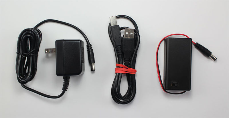
Arduino Power Supply
The Arduino Uno needs a power source in order for it to operate and can be powered in a variety of ways. You can do what most people do and connect the board directly to your computer via a USB cable. If you want your project to be mobile, consider using a 9V battery pack to give it juice. The last method would be to use a 9V AC power supply.
Arduino Breadboard
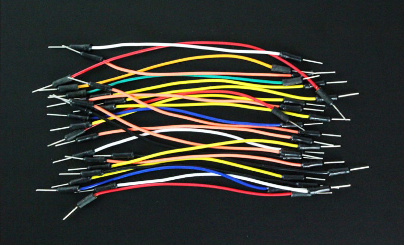
Another very important item when working with Arduino is a solderless breadboard. This device allows you to prototype your Arduino project without having to permanently solder the circuit together. Using a breadboard allows you to create temporary prototypes and experiment with different circuit designs. Inside the holes (tie points) of the plastic housing, are metal clips which are connected to each other by strips of conductive material.
On a side note, the breadboard is not powered on its own and needs power brought to it from the Arduino board using jumper wires. These wires are also used to form the circuit by connecting resistors, switches and other components together.
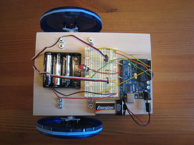
Here is a visual of what a completed Arduino circuit looks like when connected to a breadboard.
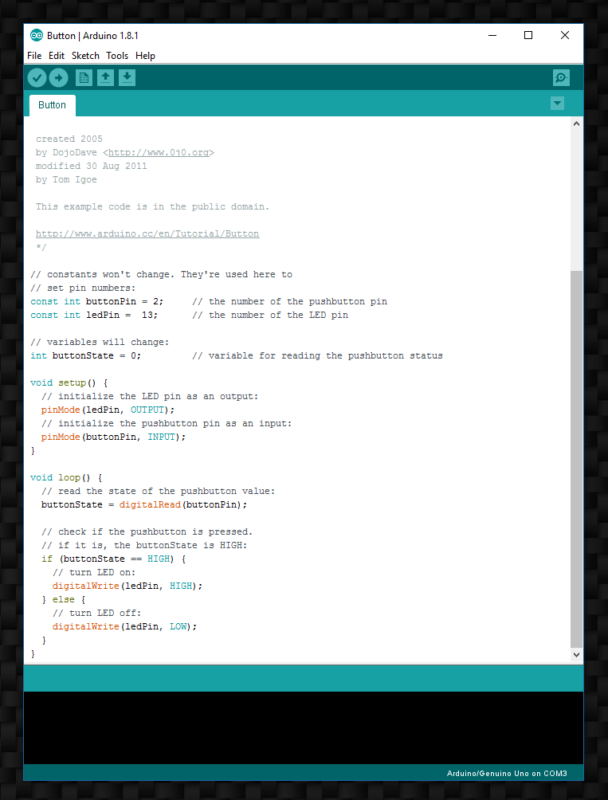
How To Program Arduino
Once the circuit has been created on the breadboard, you’ll need to upload the program (known as a sketch) to the Arduino. The sketch is a set of instructions that tells the board what functions it needs to perform. An Arduino board can only hold and perform one sketch at a time. The software used to create Arduino sketches is called the IDE which stands for Integrated Development Environment. The software is free to download and can be found at https://www.arduino.cc/en/Main/Software
Every Arduino sketch has two main parts to the program:
void setup() – Sets things up that have to be done once and then don’t happen again.
void loop() – Contains the instructions that get repeated over and over until the board is turned off.
Arduino Projects
You may be wondering what an Arduino board can do besides blink an LED. Below are some example projects which help to showcase how truly amazing this board is and the capabilities of it. If you’re looking for more project ideas, check out sites such as Instructables or Make Magazine which are loaded with helpful tutorials.
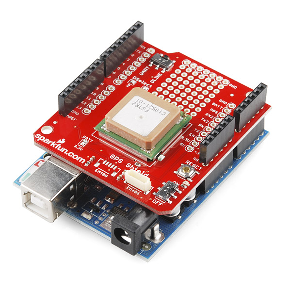
If you want to add a very specific functionality to your Arduino, you will need to use a shield. Arduino shields plug into the top of the Arduino board and can add capabilities such as WiFi, Bluetooth, GPS and much more. There are literally hundreds of shields to choose from and here are a few examples.
GPS Shield Plugged into Arduino Uno – Sparkfun.com
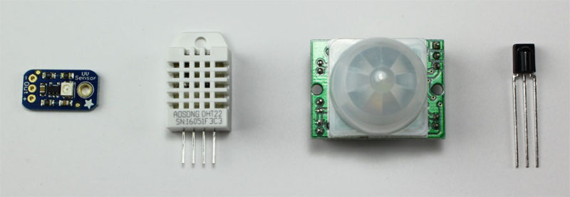
Arduino Sensors
If you want your Arduino to sense the world around it, you will need to add a sensor. There are a wide range of sensors to choose from and they each have a specific purpose. Below you will find some of the commonly used sensors in projects.
.png "Menu")